RFID技术现在都非常成熟和应用广泛,今天我们就来看看这个RFID如何实现读取里面的数据,看看RFID模块是什么模样的。
实验效果
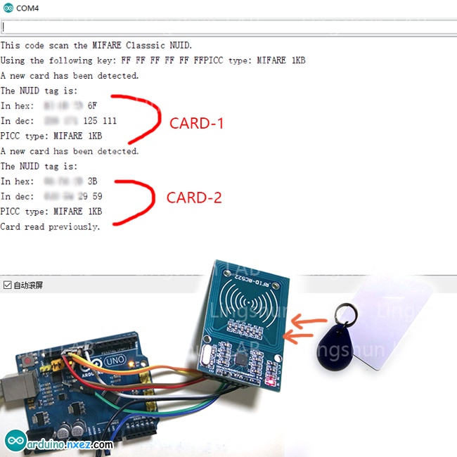
在串口监控器里面,我们把IC卡放在模块上,能读出储存在里面的数据,程序就是这样来核对与我们数据库是否匹配,如果对得上,就开门,对不上肯定打死都不开。
BOM表
Arduino Uno * 1
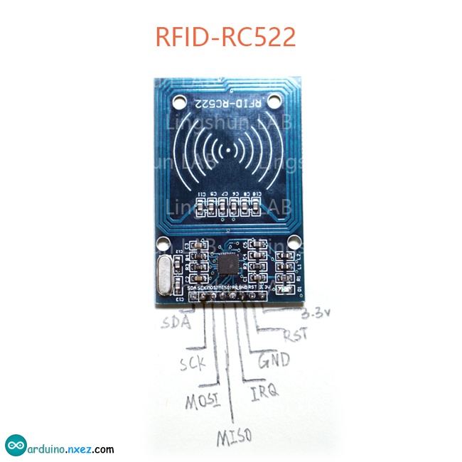
RFID-RC522 模块 * 1
IC卡 * 1-2
跳线若干
接线
Arduino Uno <—> RFID-RC522
10 <—> SDA
13 <—> SCK
11 <—> MOSI
12 <—> MISO
null <—> IRQ
GND <—> GND
9 <—> RST
3.3V <—> 3.3V
程序
我们需要用到RFID-RC522的库
下载:https://github.com/miguelbalboa/rfid
具体如何操作,再次说一下,下载解压到Arduino IDE的安装路径里的库文件夹libraries
当然我们还有第二种更新库的方法,不过这得用最新版的Arduino IDE ,
在菜单栏找到如下:
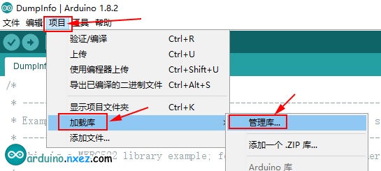
点开管理库,在搜索栏里输入RC522,找到图中的库,点击安装(我这图是已经安装过啦)

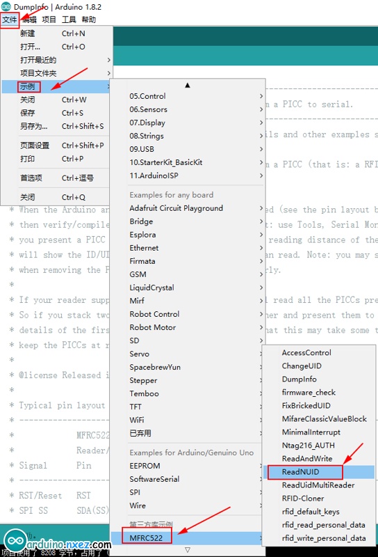
安装好库我们就可以直接使用例子里的程序
这里贴出程序:
/*
 * --------------------------------------------------------------------------------------------------------------------
 * Example sketch/program showing how to read data from a PICC to serial.
 * --------------------------------------------------------------------------------------------------------------------
 * This is a MFRC522 library example; for further details and other examples see: https://github.com/miguelbalboa/rfid
 *
 * Example sketch/program showing how to read data from a PICC (that is: a RFID Tag or Card) using a MFRC522 based RFID
 * Reader on the Arduino SPI interface.
 *
 * When the Arduino and the MFRC522 module are connected (see the pin layout below), load this sketch into Arduino IDE
 * then verify/compile and upload it. To see the output: use Tools, Serial Monitor of the IDE (hit Ctrl+Shft+M). When
 * you present a PICC (that is: a RFID Tag or Card) at reading distance of the MFRC522 Reader/PCD, the serial output
 * will show the ID/UID, type and any data blocks it can read. Note: you may see "Timeout in communication" messages
 * when removing the PICC from reading distance too early.
 *
 * If your reader supports it, this sketch/program will read all the PICCs presented (that is: multiple tag reading).
 * So if you stack two or more PICCs on top of each other and present them to the reader, it will first output all
 * details of the first and then the next PICC. Note that this may take some time as all data blocks are dumped, so
 * keep the PICCs at reading distance until complete.
 *
 * @license Released into the public domain.
 *
 * Typical pin layout used:
 * -----------------------------------------------------------------------------------------
 *             MFRC522      Arduino       Arduino   Arduino    Arduino          Arduino
 *             Reader/PCD   Uno/101       Mega      Nano v3    Leonardo/Micro   Pro Micro
 * Signal      Pin          Pin           Pin       Pin        Pin              Pin
 * -----------------------------------------------------------------------------------------
 * RST/Reset   RST          9             5         D9         RESET/ICSP-5     RST
 * SPI SS      SDA(SS)      10            53        D10        10               10
 * SPI MOSI    MOSI         11 / ICSP-4   51        D11        ICSP-4           16
 * SPI MISO    MISO         12 / ICSP-1   50        D12        ICSP-1           14
 * SPI SCK     SCK          13 / ICSP-3   52        D13        ICSP-3           15
 */

#include <SPI.h>
#include <MFRC522.h>

#define RST_PIN         9          // Configurable, see typical pin layout above
#define SS_PIN          10         // Configurable, see typical pin layout above

MFRC522 mfrc522(SS_PIN, RST_PIN);  // Create MFRC522 instance

void setup() {
	Serial.begin(9600);		// Initialize serial communications with the PC
	while (!Serial);		// Do nothing if no serial port is opened (added for Arduinos based on ATMEGA32U4)
	SPI.begin();			// Init SPI bus
	mfrc522.PCD_Init();		// Init MFRC522
	mfrc522.PCD_DumpVersionToSerial();	// Show details of PCD - MFRC522 Card Reader details
	Serial.println(F("Scan PICC to see UID, SAK, type, and data blocks..."));
}

void loop() {
	// Look for new cards
	if ( ! mfrc522.PICC_IsNewCardPresent()) {
		return;
	}

	// Select one of the cards
	if ( ! mfrc522.PICC_ReadCardSerial()) {
		return;
	}

	// Dump debug info about the card; PICC_HaltA() is automatically called
	mfrc522.PICC_DumpToSerial(&(mfrc522.uid));
}
文章转自这里。

发表评论
要发表评论,您必须先登录。